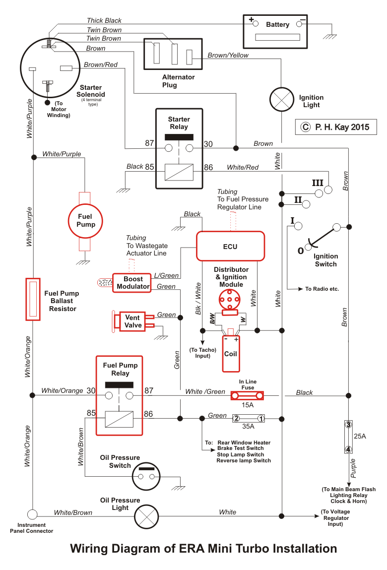
Mini Turbo Installation - Wiring Diagram and Circuit Description
Please Note: On the following diagram, all items that are unique to the turbo installation are outlined in red.
Circuit Description
When the ignition key is set to position II, normal ‘Ignition On’, Battery positive is supplied, via the white wire, to the ignition Coil, ECU, and to one side of fuse 1–2 in the fuse box (the top fuse). The engine has, therefore, all requirements for starting. In addition, with power at fuse 1–2, the coil of the Fuel Pump Relay has battery volts at its coil terminal 86. The other side of the coil, at terminal 85, is however not connected to chassis until the oil pressure switch closes, which only occurs when the engine starts and sufficient oil pressure has been generated. The Oil Pressure Lamp has battery positive at one side, via the white wire. Its other side is connected to near chassis via the Fuel Pump and its associated Ballast Resistor. The lamp will therefore illuminate, indicating low oil pressure. (Note: Since the current taken by the bulb is very small, the combined voltage drop across the Ballast Resistor and stationery Fuel Pump windings will be extremely small.)
When the Ignition Switch is set to position III, the ‘Start’ position, battery positive is now also applied to the coil of the Starter Relay at terminal 86, via the white/red wire. Since the other side of the coil at 85 is connected to chassis, the relay energises. Battery positive is therefore switched to the Solenoid, via contacts 30 and 87 which then supplies the Starter Motor. Whilst the Starter is energised, a separate auxiliary contact on the Solenoid, feeds power to the Fuel Pump. The pump now runs, filling the carburettor bowl with fuel.
Whilst the Ignition Switch is at position III, connection is still made to the contact at position II, the normal ‘Ignition On’ position, thus maintaining the initial ‘Ignition ON’ conditions previously described. The Oil Pressure Lamp will, however, extinguish whilst the Solenoid is energised, as battery positive is applied to both sides of the lamp in this condition.
After the engine starts, the ignition key is released and returns under spring tension to position II. The ignition supply remains connected, but the supply to the Solenoid and therefore the Fuel Pump is removed. The engine continues to run however, using the fuel in the carburettor bowl, which will last for approximately 30 seconds. Meanwhile, as soon as oil pressure reaches approximately 5psi, the Oil Pressure Switch closes, thus energising the Fuel Pump Relay. Its contacts, between 87 and 30 therefore close, switching a permanent battery supply, via the In Line fuse and the Fuel Pump Ballast Resistor, to the Fuel Pump, which runs at a reduced voltage to prevent overheating. The voltage at terminal 30 of the Fuel Pump Relay is also routed, via the white/orange wire, to the Oil Pressure Lamp. This lamp is now supplied with battery positive at both sides, causing it to extinguish.
In the event of the engine stopping for any reason, whilst the Ignition Switch is still at position II, e.g. in a crash, then the Oil Pressure Switch will open, causing the Fuel Pump Relay to de-energise, which will therefore remove the battery supply from the Fuel Pump and return the near chassis connection to the Oil Pressure lamp, the latter then illuminating.